How to connect 10k potentiometer in circuit, A potentiometer, or “pot,” is a variable resistor that can be used to adjust the resistance in a circuit. A 10k potentiometer has a resistance of 10,000 ohms. Here’s a general guide on how to connect a 10k potentiometer in a circuit:
How to connect 10k potentiometer in circuit:
Standard 3-terminal Potentiometer:
- Identify the Pins:
- A standard potentiometer has three pins. Let’s label them A, B, and C.
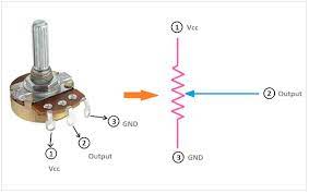
- Pin A: Connect this to the voltage source (e.g., 5V).
- Pin B: Connect this to the input or output of your circuit.
- Pin C: Connect this to the ground (0V).
- A standard potentiometer has three pins. Let’s label them A, B, and C.
- Voltage Source and Ground Connection:
- Connect Pin A to the positive side of your power supply (e.g., 5V).
- Connect Pin C to the ground or 0V of your power supply.
- Input/Output Connection:
- Connect Pin B to the part of your circuit where you want the variable resistance.
- Adjustment:
- By turning the knob on the potentiometer, you can vary the resistance between Pin B and Pin C.
Example Circuit:
Let’s say you have an LED circuit where you want to vary the brightness. You could connect the potentiometer like this:
- Pin A of the potentiometer to +5V.
- Pin C of the potentiometer to GND.
- Pin B of the potentiometer connected to one leg of a resistor, the other leg of the resistor connected to the anode (longer lead) of the LED.
- The cathode (shorter lead) of the LED connected to GND.
This way, as you turn the potentiometer, you’re adjusting the resistance in series with the LED, controlling its brightness.
Remember, the specific connections can vary depending on your application, so adapt these instructions based on the requirements of your circuit. Always refer to the datasheet of your specific potentiometer model for accurate information.
What is the connection of 10k potentiometer?
A 10k potentiometer typically has three terminals or pins. Let’s label them as follows:
- Terminal 1 (A or CW): This is the first terminal and is often labeled “A” or “CW” (clockwise). Connect this terminal to the positive side of your power supply or voltage source.
- Terminal 2 (B or Wiper): This is the middle terminal and is often labeled “B” or “Wiper.” Connect this terminal to the input or output of your circuit where you want the variable resistance.
- Terminal 3 (C or CCW): This is the third terminal and is often labeled “C” or “CCW” (counterclockwise). Connect this terminal to the ground (0V) of your power supply.
Here’s a simple representation:
scssCopy code
(A) ----|---- (B) ----|---- (C) | Wiper
In a typical potentiometer, turning the knob changes the resistance between terminals A and B and between terminals B and C. The resistance between A and C remains constant.
To use a 10k potentiometer in a circuit, you would typically connect the ends (A and C) to your power supply (e.g., 5V and GND) and use the wiper (B) as the variable resistor in your circuit. The resistance between A and B and between B and C will change as you turn the knob, allowing you to control the voltage or current in your circuit.
How do you connect a potentiometer to a circuit?
Connecting a potentiometer to a circuit involves understanding the three terminals of the potentiometer and appropriately integrating it into the circuit. Here’s a step-by-step guide:
Materials Needed:
- Potentiometer: You mentioned a 10k potentiometer.
- Breadboard and Jumper Wires: For prototyping.
Steps:
- Identify the Potentiometer Terminals:
- A standard potentiometer has three terminals – usually labeled A, B, and C.
- Terminal A (or CW) is one end.
- Terminal B (or Wiper) is the middle.
- Terminal C (or CCW) is the other end.
- A standard potentiometer has three terminals – usually labeled A, B, and C.
- Understand the Circuit:
- Determine where in your circuit you want variable resistance or voltage control.
- Connect the Potentiometer to Power:
- Connect Terminal A to the positive side of your power supply (e.g., 5V).
- Connect Terminal C to the ground (0V) of your power supply.
- Connect the Potentiometer to the Circuit:
- Connect Terminal B to the input or output of your circuit where you want the variable resistance.
- Complete the Circuit:
- Ensure the rest of your circuit is appropriately connected, and the potentiometer is in series with the component you want to control (e.g., LED, motor, etc.).
- Adjustment:
- As you turn the potentiometer knob, the resistance between terminals A and B and between B and C will change, affecting the behavior of your circuit.
Example LED Circuit:
Here’s a simple example where you control the brightness of an LED:
- Connect Terminal A to +5V.
- Connect Terminal C to GND.
- Connect Terminal B to a series resistor, and then connect the other end of the resistor to the anode (longer lead) of the LED.
- Connect the cathode (shorter lead) of the LED to GND.
By turning the potentiometer, you vary the resistance in series with the LED, changing its brightness.
Always refer to the datasheet of your specific potentiometer model for accurate information, and adapt these instructions based on the requirements of your circuit.
What are the 3 pins on a potentiometer?
A potentiometer typically has three pins or terminals. These are commonly labeled as follows:
- Terminal 1 (A or CW): This is the first terminal, often labeled as “A” or “CW” (Clockwise). Connect this terminal to the positive side of your power supply or voltage source.
- Terminal 2 (B or Wiper): This is the middle terminal, often labeled as “B” or “Wiper.” Connect this terminal to the input or output of your circuit where you want the variable resistance.
- Terminal 3 (C or CCW): This is the third terminal, often labeled as “C” or “CCW” (Counterclockwise). Connect this terminal to the ground (0V) of your power supply.
The wiper terminal (Terminal 2) is the movable contact that slides along the resistive element, allowing you to adjust the resistance between Terminal 1 and Terminal 3. The resistance between Terminal 1 and Terminal 2 and between Terminal 2 and Terminal 3 changes as you turn the knob or shaft of the potentiometer.
Here’s a simple representation:
scssCopy code
(A) ----|---- (B) ----|---- (C) | Wiper
Understanding these terminals is crucial when connecting a potentiometer to a circuit, as it determines how the variable resistance affects the rest of the components in the circuit.
Why 10 m long wire is used in potentiometer?
The use of a 10-meter-long wire in a potentiometer is not a fixed or standard requirement; the length of the wire used in a potentiometer can vary based on the specific application and the requirements of the experiment or circuit. The length of the wire is chosen based on the precision and sensitivity needed for the measurement or control of voltage.
In a potentiometer, the length of the wire determines the total resistance, and the wiper, as it moves along the wire, taps into a variable portion of that resistance. The longer the wire, the higher the total resistance, and the finer the control you can achieve. However, longer wires can also introduce more resistance and potential for errors in the measurement or control.
Here are some considerations:
- Precision: A longer wire allows for more precise adjustments, especially when measuring or controlling small voltage differences. This is particularly important in applications like calibration or measurement where fine adjustments are needed.
- Sensitivity: Longer wires can make the potentiometer more sensitive to small changes in resistance, which can be beneficial in certain applications.
- Voltage Drop: Longer wires can introduce more resistance and lead to voltage drop along the wire. This can affect the accuracy of the potentiometer, especially in low-voltage circuits.
- Practical Limitations: There are practical limitations to the length of wire used, considering factors like cost, space, and the specific requirements of the circuit.
In some cases, potentiometers with shorter lengths of wire may be sufficient for the desired application. It’s important to select the appropriate potentiometer based on the specific needs of your circuit or experiment. If you have a specific application in mind, you may want to consult the relevant technical specifications or guidelines to determine the suitable length of the potentiometer wire.
More story in Hindi to read:
Moral stories in Hindi for class