How to connect 16*2 lcd with arduino, Connecting a 16×2 LCD (Liquid Crystal Display) with an Arduino is a common and straightforward process. Here are the general steps:
How to connect 16*2 lcd with arduino:
Components Needed:
- Arduino board (e.g., Arduino Uno)
- 16×2 LCD display
- Potentiometer (for contrast adjustment)
- Jumper wires
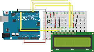
Wiring Connections:
LCD Pins:
- VSS (Pin 1): Connect to GND on Arduino.
- VDD (Pin 2): Connect to 5V on Arduino.
- VO (Pin 3): Connect to the center pin of the potentiometer.
- RS (Pin 4): Connect to digital pin on Arduino (e.g., D7).
- RW (Pin 5): Connect to GND on Arduino.
- EN (Pin 6): Connect to digital pin on Arduino (e.g., D6).
- D4 to D7 (Pins 11 to 14): Connect to digital pins on Arduino (e.g., D5 to D2).
- A (Pin 15): Connect to 5V on Arduino.
- K (Pin 16): Connect to GND on Arduino.
Potentiometer:
- Connect one outer pin to 5V on Arduino.
- Connect the other outer pin to GND on Arduino.
- Connect the center pin to VO (Pin 3) on the LCD.
Arduino Sketch:
cppCopy code
#include
Explanation:
- Include the LiquidCrystal library.
- Create a LiquidCrystal object, specifying the pins connected to RS, EN, and D4 to D7.
- In the
setupfunction, initialize the LCD with the number of columns and rows (16×2 in this case). - Use the
printorwritefunctions to display text on the LCD in thesetuporloopfunctions.
Additional Tips:
- Adjust the potentiometer to set the contrast of the display.
- Ensure that the wiring is correct, and double-check the connections.
- You can modify the code to display dynamic information based on your project requirements.
Upload the sketch to your Arduino, and you should see the specified message on the LCD.
How to connect 16 * 2 LCD to I2C module?
Connecting a 16×2 LCD to an I2C module simplifies the wiring and reduces the number of pins used on your Arduino. The I2C module typically has a PCF8574 or similar I2C expander onboard, allowing you to control the LCD using only two wires (SDA and SCL). Here are the steps to connect a 16×2 LCD to an I2C module:
Components Needed:
- Arduino board (e.g., Arduino Uno)
- 16×2 LCD display with I2C backpack/module
- Jumper wires
Wiring Connections:
LCD with I2C Module:
- Connect the SDA (data) pin on the I2C module to the SDA pin on the Arduino.
- Connect the SCL (clock) pin on the I2C module to the SCL pin on the Arduino.
- Connect the VCC pin on the I2C module to the 5V pin on the Arduino.
- Connect the GND pin on the I2C module to the GND pin on the Arduino.
Adjusting Contrast (Optional):
Some I2C modules have a potentiometer to adjust the contrast. If your module has one, connect it as follows:
- Connect the VO (contrast) pin on the LCD to the wiper (center pin) of the potentiometer.
- Connect one outer pin of the potentiometer to 5V on the Arduino.
- Connect the other outer pin of the potentiometer to GND on the Arduino.
Arduino Sketch:
You’ll need the “LiquidCrystal_I2C” library for this, which can be installed via the Arduino Library Manager.
cppCopy code
#include
Explanation:
- Include the Wire and LiquidCrystal_I2C libraries.
- Set the LCD address (you can use an I2C scanner to find it).
- Create a LiquidCrystal_I2C object, specifying the LCD address and size.
- In the
setupfunction, initialize the LCD. - Use the
printorwritefunctions to display text on the LCD in thesetuporloopfunctions.
Additional Tips:
- Ensure that the I2C address is correctly set in the code. Use an I2C scanner sketch to find the address if needed.
- If the LCD doesn’t display anything, adjust the contrast potentiometer on the I2C module.
- Confirm that your Arduino is connected to the correct I2C pins (SDA and SCL).
Upload the sketch to your Arduino, and you should see the specified message on the LCD.
How do you connect Arduino to LCD screen?
Connecting an Arduino to an LCD (Liquid Crystal Display) screen involves wiring the LCD to the Arduino and writing a program to control the display. I’ll provide a general guide for connecting a 16×2 LCD screen to an Arduino:
Components Needed:
- Arduino board (e.g., Arduino Uno)
- 16×2 LCD display
- Potentiometer (for contrast adjustment)
- Jumper wires
Wiring Connections:
LCD Pins:
- VSS (Pin 1): Connect to GND on Arduino.
- VDD (Pin 2): Connect to 5V on Arduino.
- VO (Pin 3): Connect to the center pin of the potentiometer.
- RS (Pin 4): Connect to a digital pin on Arduino (e.g., D7).
- RW (Pin 5): Connect to GND on Arduino.
- EN (Pin 6): Connect to a digital pin on Arduino (e.g., D6).
- D4 to D7 (Pins 11 to 14): Connect to digital pins on Arduino (e.g., D5 to D2).
- A (Pin 15): Connect to 5V on Arduino.
- K (Pin 16): Connect to GND on Arduino.
Potentiometer:
- Connect one outer pin to 5V on Arduino.
- Connect the other outer pin to GND on Arduino.
- Connect the center pin to VO (Pin 3) on the LCD.
Arduino Sketch:
cppCopy code
#include
Explanation:
- Include the LiquidCrystal library.
- Create a LiquidCrystal object, specifying the pins connected to RS, EN, and D4 to D7.
- In the
setupfunction, initialize the LCD with the number of columns and rows (16×2 in this case). - Use the
printorwritefunctions to display text on the LCD in thesetuporloopfunctions.
Additional Tips:
- Adjust the potentiometer to set the contrast of the display.
- Ensure that the wiring is correct, and double-check the connections.
- You can modify the code to display dynamic information based on your project requirements.
Upload the sketch to your Arduino, and you should see the specified message on the LCD.
What is LCD begin 16 2 in Arduino?
In Arduino programming, the lcd.begin(16, 2) line is part of the setup code for an LCD (Liquid Crystal Display) using the LiquidCrystal library. Let’s break down what this line does:
cppCopy code
#include
#include: This line includes the LiquidCrystal library, which provides functions to control LCDs.LiquidCrystal lcd(7, 6, 5, 4, 3, 2);: This line declares an object namedlcdof the typeLiquidCrystal. It specifies the pins to which the RS, EN, and D4 to D7 pins of the LCD are connected on the Arduino. Adjust these pin numbers based on your actual wiring.lcd.begin(16, 2);: This line initializes the LCD. Thebeginfunction is used to configure the LCD with the specified number of columns and rows. In this case, it’s a 16×2 LCD, meaning it has 16 columns and 2 rows. You should adjust these parameters based on the specifications of your LCD.
So, lcd.begin(16, 2) is telling the Arduino that the connected LCD has 16 columns and 2 rows, allowing the Arduino to properly communicate with and control the display. This information is crucial for the library to understand the layout of the LCD and how to interact with it.
Which IC is used in 16 * 2 LCD module?
A common type of IC (integrated circuit) used in 16×2 LCD modules is the HD44780 or a compatible controller. The HD44780 is a popular LCD controller that provides a standard interface for alphanumeric LCD modules. It’s widely used in the industry, and many 16×2 LCDs, especially those without an I2C backpack or module, are based on this controller.
The HD44780 controller supports a parallel interface for communication with microcontrollers like the Arduino. It allows you to control the content displayed on the LCD, handle cursor positioning, and manage other aspects of the display.
When using an LCD with an I2C backpack or module (as mentioned in a previous response), the backpack often includes an additional IC, such as the PCF8574 or similar, which acts as an I2C expander. This expander allows the Arduino to communicate with the LCD using only two wires (SDA and SCL) instead of the larger number of parallel interface wires.
If you have an LCD without an I2C module, you might need to interact directly with the HD44780 controller using more pins on your microcontroller for data and control signals. Always refer to the datasheet of the specific LCD module you are using for accurate information about the controller and its specifications.
More story in Hindi to read:
Moral stories in Hindi for class